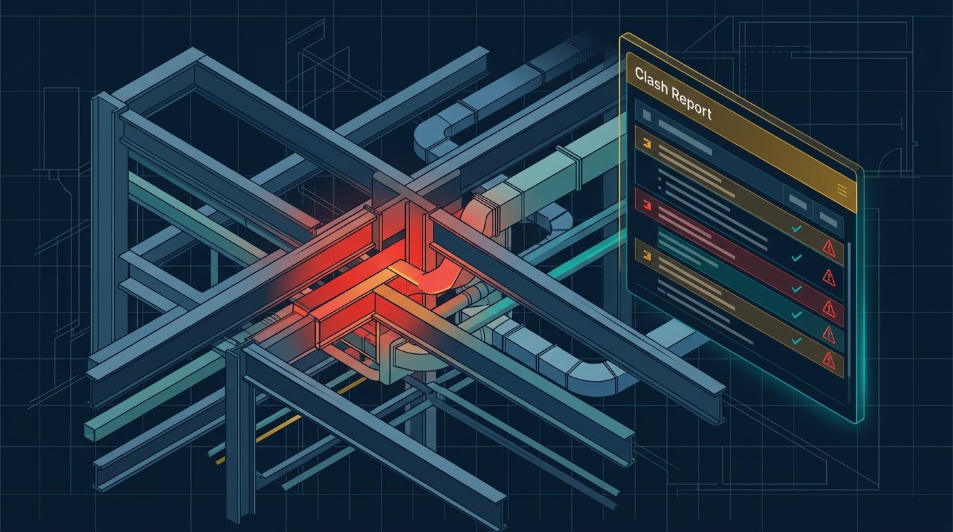
Fire protection is the one MEP system that can't afford a coordination mistake - a sprinkler head that ends up behind ductwork, or a hydrant riser that clashes with structure, isn't just a rework cost. It's a life-safety system that has to actually work. Modeling it in BIM, coordinated with everything around it, is how that gets verified before installation.
Why Model Fire Protection in BIM
Fire fighting systems route through the same congested ceiling voids and risers as every other MEP discipline, but with less tolerance for compromise: sprinkler coverage and hydrant placement are governed by code, not design preference. Modeling the full system in BIM - pump room, risers, branch piping, sprinkler heads, hydrant cabinets - lets it be checked for both physical clashes and code coverage before a single pipe is installed.
Sprinkler Systems
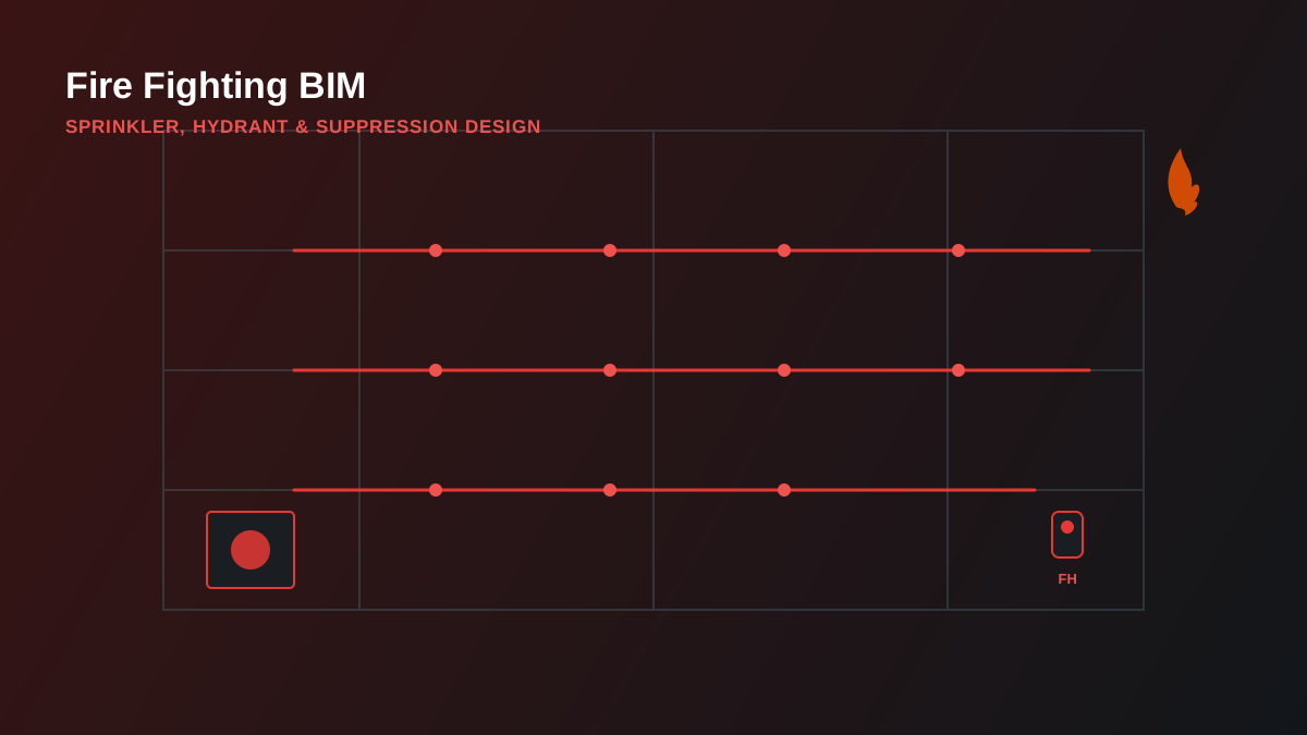
Sprinkler design starts with occupancy hazard classification, which sets the required coverage area and discharge density per head. In BIM, that translates into a modeled network of wet-pipe (or dry-pipe, where freezing is a risk) branch lines, sized and routed to hit code-required spacing across every covered space - then checked against ceiling grids, ductwork, and structure in the same coordination pass as every other MEP system.
Hydrant Systems
Fire hydrant systems - internal hose reels, landing valves, and external hydrants - are modeled with their own dedicated riser and pump feed, sized for the required flow and pressure at the most remote point on the system. Placement is driven by travel distance requirements: every part of the building needs to fall within reach of a hydrant point, which is as much a layout exercise as a modeling one.
Gas & Clean-Agent Suppression
Spaces that can't be protected by water - server rooms, electrical switchgear, archives - typically use a gas or clean-agent suppression system (CO₂ or FM-200/Novec). These are modeled as a sealed-room system: agent cylinders, discharge nozzles, and detection tied to the room's exact volume, since the agent concentration required is a direct function of the space being protected.
Coordinating Fire Protection with MEP
Fire protection is usually the last system routed in a coordination sequence - sprinkler branch lines are the most flexible MEP system to reroute around everything already fixed above the ceiling. But "flexible to route" doesn't mean "low priority to check": every fire protection element still has to clear structure, ductwork and cable containment, and still hit its required coverage once rerouted. That's why fire protection gets run through the same clash detection process as the rest of the MEP scope, not treated as an afterthought once everything else is locked.
From our project experience: we've delivered full fire fighting design and modeling on commercial buildings including sheet generation for site installation - the same coordinated-with-MEP approach applies whether it's a single building or a multi-building industrial site.
Standards We Design To
Fire protection design has to match the governing code for the project's jurisdiction - NBC India, NFPA (US-influenced markets), or VdS (European insurance-driven standards) most commonly. We design and model to whichever standard applies, coordinated with the architectural, structural and MEP models throughout. Our fire fighting BIM design service covers sprinkler, hydrant and suppression system modeling end to end - get a free quote for your project's fire protection scope.